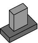
Jumper On Circuit Complete |
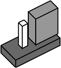
Jumper Off But Stored Circuit Not Complete |
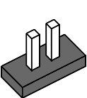
Jumper Removed Circuit Not Complete |
Explanation Of JumpersWhen a jumper is soldered to a printed circuit board, there will be a number identifying the jumper printed next to it. Sometimes they say J1, J2, etc. and sometimes they JP1, JP2, etc. Many circuit boards have diagrams printed on them explaining what the various jumpers positions are for. The following diagram shows various jumper positions. A jumper is equivalent to an electrical switch. It has a black plastic cover, but inside the cover is a metal connector. When the shunt is positioned over two pins, it completes an electrical circuit. Jumpers are used instead of switches because they are very small, inexpensive and do not need to be set frequently. Completely removing the shunt is equivalent to placing it over only 1 pin. In either case, the electrical circuit is open which is like a switch being turned off. |
Jumper On Circuit Complete |
Jumper Off But Stored Circuit Not Complete |
Jumper Removed Circuit Not Complete |
| Home - Drivers - Support - Products - Links - Contacts - Shop - Search | |
| Copyright � 2000 Mustek, Inc. | |