 | Document # 5054 |
        |
MFS-12000SP, Paragon 1200 SP |
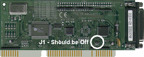
| The Paragon 1200 SP previously shipped with a DTC-3181A SCSI interfacecard. The 3181A SCSI card has one jumper located at J1 which you shouldset to the Off position if it has not already been done.
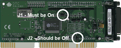
DTC-3181A SCSI Card We recently began shipping the 1200 SP scanner with a DTC-3181E SCSIinterface card. The 3181E SCSI card has two jumpers; one at J1 andanother at J2. You should set the jumper at J2 to the Off position on thiscard. DO NOT REMOVE J1or the card will not work. J1 must be set to the on position. Several shipmentsof the 1200 SP left our warehouse with the wrong instruction sheet in thebox. If you have a DTC-3181E and the InstallationRoadmap says to remove J1, ignore that step of the instructions.
DTC-3181E SCSI Card Explanation Of JumpersWhen a jumper is soldered to a printed circuit board, there will bea number identifying the jumper printed next to it. Sometimes they sayJ1, J2, etc. and sometimes they JP1, JP2, etc. Many circuit boards havediagrams printed on them explaining what the various jumpers positionsare for. The following diagram shows various jumper positions. A jumper is equivalentto an electrical switch. It has a black plastic cover, but inside the coveris a metal connector. When the shunt is positioned over two pins, it completesan electrical circuit. Jumpers are used instead of switches because theyare very small, inexpensive and do not need to be set frequently. Completely removing the shunt is equivalent to placing it over only1 pin. In either case, the electrical circuit is open which is like a switchbeing turned off. |
Jumper On Circuit Complete |
Jumper Off But Stored Circuit Not Complete |
Jumper Removed Circuit Not Complete |
| Mustek and the Mustek logo are trademarks and registered trademarksof Mustek, Incorporated. Any use without the express written permissionof Mustek is forbidden. Other company and product names may be trademarksor registered trademarks. |